Fig. 1 Connection Between MCU to LCD
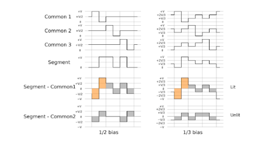
LCD can’t be driven with DC (Direct Current), it has to be driven with AC (Alternative Current) and the overall current has to be ZERO. Otherwise, the Liquid Crystal Material will be damaged sooner or later.

Fig. 2 LCD Driving Waveform
There are two types of Driver IC’s, Common Drivers and Segment Drivers. Common Drivers output signals to create the rows or numbers of lines. The Segment Drivers output the necessary signals to create the characters or columns.
The Controller IC receives data written in ASCII or JIS code from the MPU and stores this data in RAM. This data is then converted into serial character patterns and transferred to the LCD driver IC.
Drive/Controller IC is probably the most commonly found in a graphics module. This IC receives data from the MPU and stores it in RAM. Also, it accepts commands directly from the MPU for both the common and segment drivers.
A universal asynchronous receiver/transmitter (UART) is a block of circuitry responsible for implementing serial communication. Essentially, the UART acts as an intermediary between parallel and serial interfaces. On one end of the UART is a bus of eight-or-so data lines (plus some control pins), on the other is the two serial wires – RX and TX.

Fig. 3 URAT Interface
For UART Interface related products, you can also find it here.